1. Tool length compensation
The data input for CNC machining center programming requires specifying the machining center of the part in order to establish the workpiece programming coordinate system. This coordinate system is only a workpiece coordinate system, with the zero point on the workpiece. The length compensation of CNC machining center is only related to the Z coordinate, unlike the programming zero point in the X and Y planes; The tool is positioned by the spindle taper hole without changing, and the length of each tool at the zero point of the Z coordinate is different.
 The CNC machining center needs to drill a hole with a depth of 50mm, and then tap a hole with a depth of 45mm. Using a 250mm long drill bit and a 350mm long tap, the drill bit is used to drill a hole with a depth of 50mm. At this point, the machining center has already set the zero point of the workpiece. When replacing the tap for tapping, if both tools start processing from the set zero point, the tap will be too long to tap due to being longer than the drill bit, causing damage to the tool and workpiece.
If tool compensation is set, Compensate the length of the tap and drill bit. After setting the zero point of the machining center, even if the length of the tap and drill bit is different, due to the existence of compensation, the zero point Z coordinate has automatically compensated the length of the tap to Z+(or Z) when calling the tap to work, ensuring the accuracy of the machining zero point.
2. Tool radius compensation
CNC machining centers have tool radius compensation, and when programming, the diameter of the tool can be disregarded. Tool length compensation is applicable to all tools, while tool radius compensation is generally only used for milling cutters; When the milling cutter processes the outer or inner contour of the workpiece, tool radius compensation is used. When using the end face milling cutter to process the end face of the workpiece, only tool length compensation is required.
The tool radius compensation of CNC machining centers is a relatively difficult instruction to understand and use, so they are not willing to use it in programming. In fact, understanding and mastering it can bring great convenience to programming and machining; When preparing a program to process the shape of a workpiece with a milling cutter, the first step is to carefully calculate the coordinate values based on the overall dimensions of the workpiece and the radius of the tool to determine the path taken by the tool center. The tool radius used is only the radius value of this milling cutter.
After completing the program, it is found that this milling cutter is not suitable for switching to other diameter cutters. At this point, it is necessary to recalculate the coordinate values of the path taken by the tool center, This is simply too difficult to recalculate for molds with complex shapes. The contour processing of a workpiece can be divided into rough machining and precision machining. After the rough machining program is programmed, the rough machining is completed.
After rough machining, the overall dimensions of the workpiece have changed, and the workload of calculating the center coordinates of the precision machining tool is too large; If tool radius compensation is used, the tool radius can be ignored and programmed according to the workpiece size. Then, the tool radius is used as radius compensation and placed in the radius compensation register. Temporary replacement of milling cutters or rough and fine machining can be carried out. Simply changing the tool radius compensation value can control the size of the workpiece's external dimensions, and there is basically no need to make any modifications to the program.
3. Offset compensation of fixtures
Machining center fixture offset can be used without considering the position of the workpiece fixture. When CNC machining centers process small workpieces, the fixture can clamp several workpieces at a time, without considering the coordinate zero points of each workpiece during programming.
Simply program according to their respective programming zero points, and then use fixture offset to move the programming zero points on each workpiece; The fixture offset is executed using the fixture offset commands G54 to G59, or the coordinate system can be set using the G92 command; After one workpiece is processed, use G92 to reset the new workpiece coordinate system when processing the next workpiece.

 Stainless steel cnc machining parts China Metal Parts Services - CNC Machining Parts Supplier
World Class Quality Products with Competitive Global Pricing and On-Time Delivery. OEM/ODM Manufacturing by Self-Owned ISO 9001 Certified Factory. Send Enquiry Now! More
Stainless steel cnc machining parts China Metal Parts Services - CNC Machining Parts Supplier
World Class Quality Products with Competitive Global Pricing and On-Time Delivery. OEM/ODM Manufacturing by Self-Owned ISO 9001 Certified Factory. Send Enquiry Now! More  customized metal board cnc parts OEM Custom Cnc Milling Turning Stainless Steel Aluminum Brass Metal Parts More
  electric motorcycle cnc milling turning metal parts Custom CNC turning milling machining aluminum service More
  Precision Cnc Turning Milling Machining Atv/Utv Parts & Accessories Precision Cnc Turning Milling Machining Atv/Utv Parts & Accessories More
  the head of custom spray gun Custom CNC Machining Service Precision Titanium Brass Stainless Steel More
 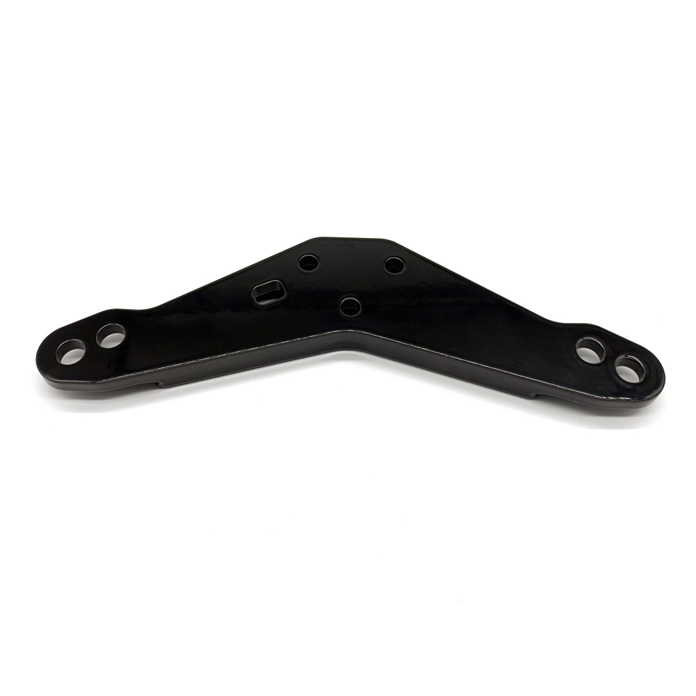 CNC Machining Parts Manufacturer Stainless Steel Aluminum CNC Mechanical Parts Precision CNC Turning Steel Parts ,CNC Machine Part More
 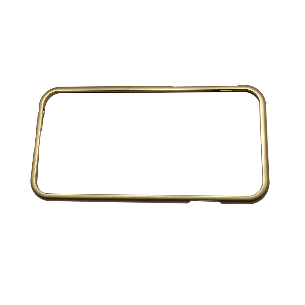 cnc milling machining turning spare parts mechanical parts China Metal Parts Services - CNC Machining Parts Supplier World Class Quality Products with Competitive Global Pricing and On-Time Delivery. OEM/ODM Manufacturing by Self-Owned ISO 9001 Certified Factory. Send Enquiry Now! More
 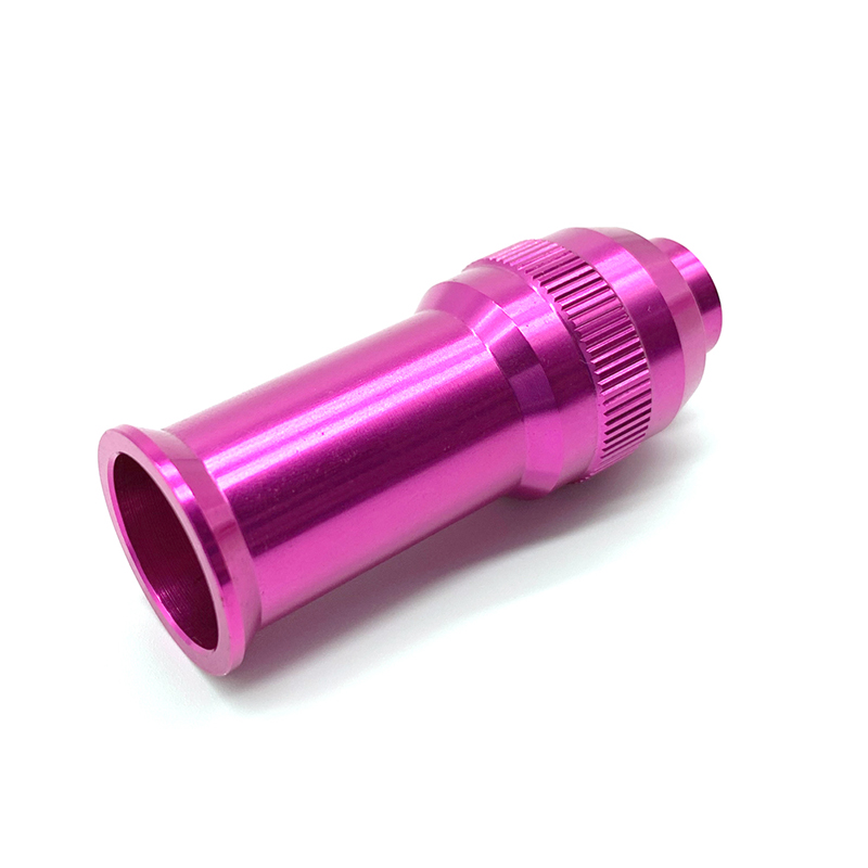 CNC Machining Precision Parts Full Shift Switch Invisible Switch China Metal Parts Services - CNC Machining Parts Supplier World Class Quality Products with Competitive Global Pricing and On-Time Delivery. OEM/ODM Manufacturing by Self-Owned ISO 9001 Certified Factory. Send Enquiry Now! More
 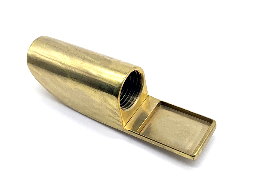 CNC machining small aluminum machined metal wheel gear parts China Metal Parts Services - CNC Machining Parts Supplier World Class Quality Products with Competitive Global Pricing and On-Time Delivery. OEM/ODM Manufacturing by Self-Owned ISO 9001 Certified Factory. Send Enquiry Now! More
  the customized metal parts of toy model car wheel hub we are specialized in prodicing all kinds of metal parts applying to building Material Shops, Manufacturing plant, and so forth so on More
  High Precision Parts Cnc Turning Machining Aluminum OEM ODM CNC Drilling Milling Machining Service We provide CNC drilling services that can process small and large batches of components of any complexity. We use different types of drilling machines (vertical, bench, radial) to drill holes with a diameter of up to 7 centimeters, and can achieve simple or complex patterns. This manufacturing method is applicable to metals and alloys (aluminum, steel, copper, etc.) and polymers More
  High Precision Parts Cnc Turning Machining Aluminum OEM ODM CNC Drilling Milling Machining Service china manufacturer professional made precision profile aluminum swiss machining cnc drilling parts More
  Customized Pen Shell we provide CNC machining service,just sending us a drawing for quote. More
 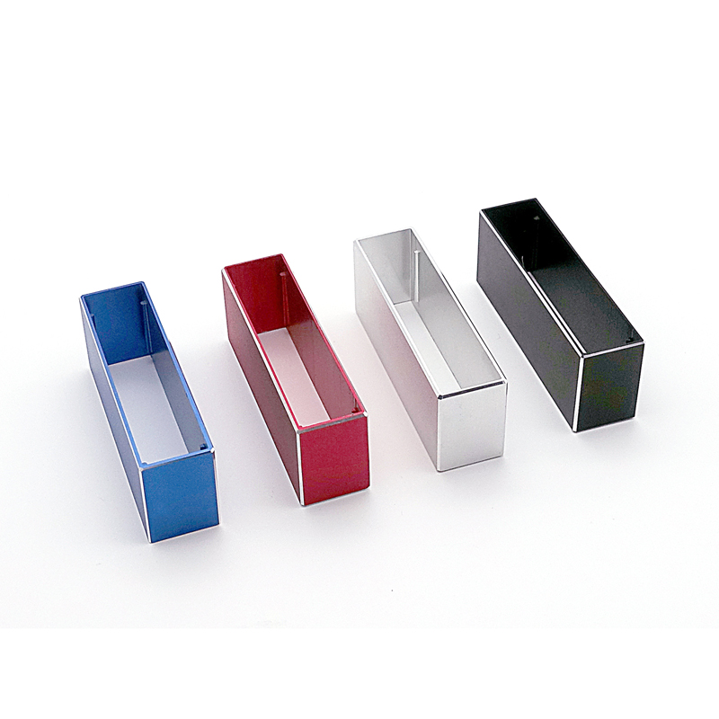 the shell of portable battery ,the customized metal housing sent us the drawings and we give you a appropriate quote More
 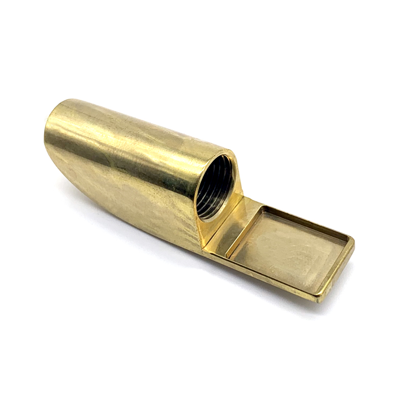 the metal cap of pen ,none-standard cap we are chinese manufacturer ,we provide competetive price.we can produce CNC parts and make a polishing. More
 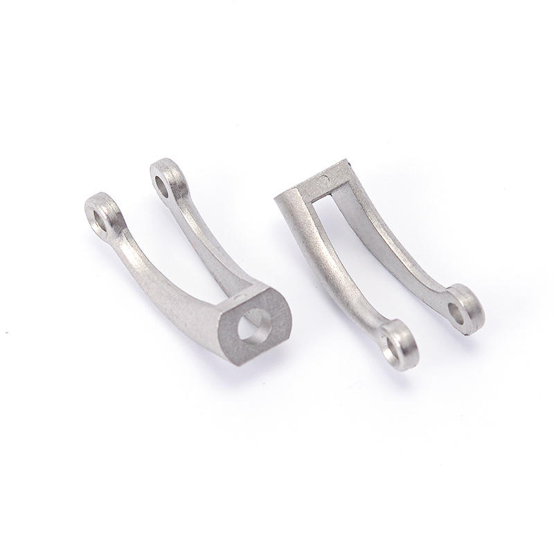 What principles should be followed in the arrangement of CNC machining sequence? More
 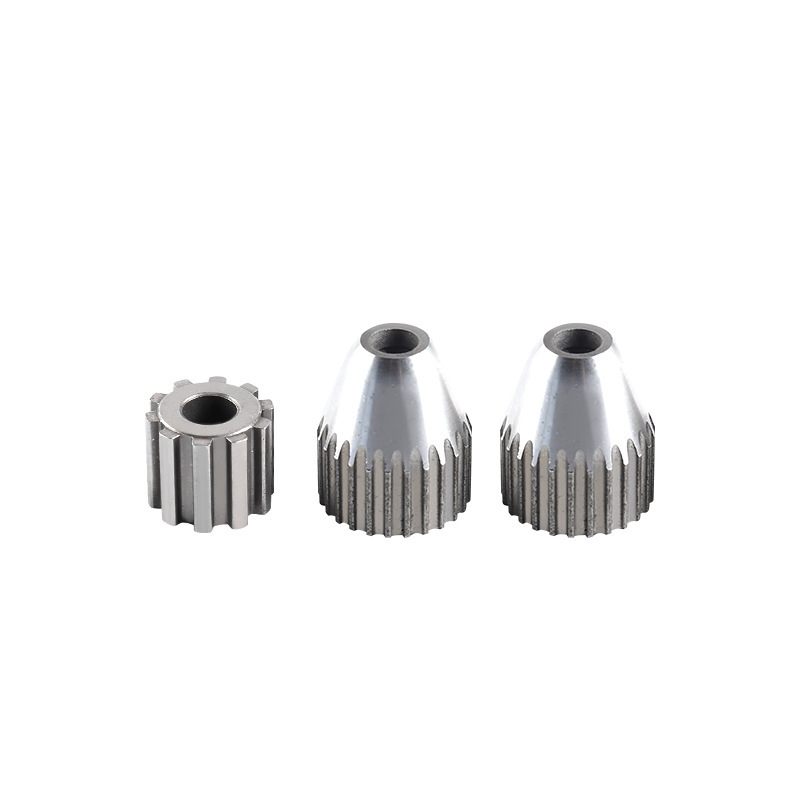 Technology Application For CNC More
  Basic composition of CNC lathe More
  Selection principles for CNC More
  The Fetures Of CNC More
  CNC MACHINING SERVICE-PROCESSING MACHINERY FEATURES More